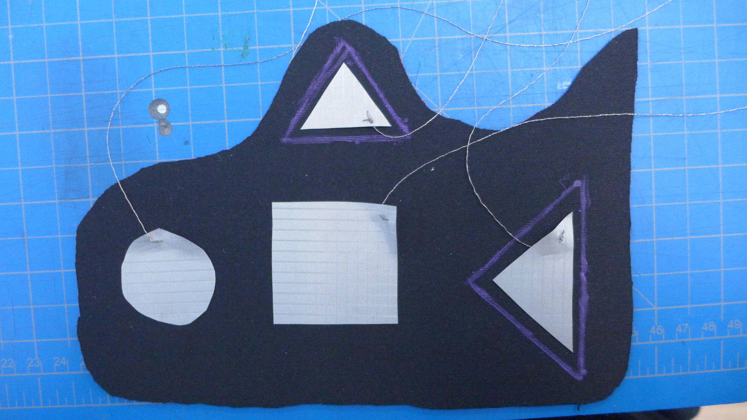
For this project, I made a textile interface that acts as a controller for Ableton Live. This project was an exploration in soft materials and rapid prototyping over the course of a weekend. You can see the full documentation of the process here.
I used the following technologies and softwares:
Arduino
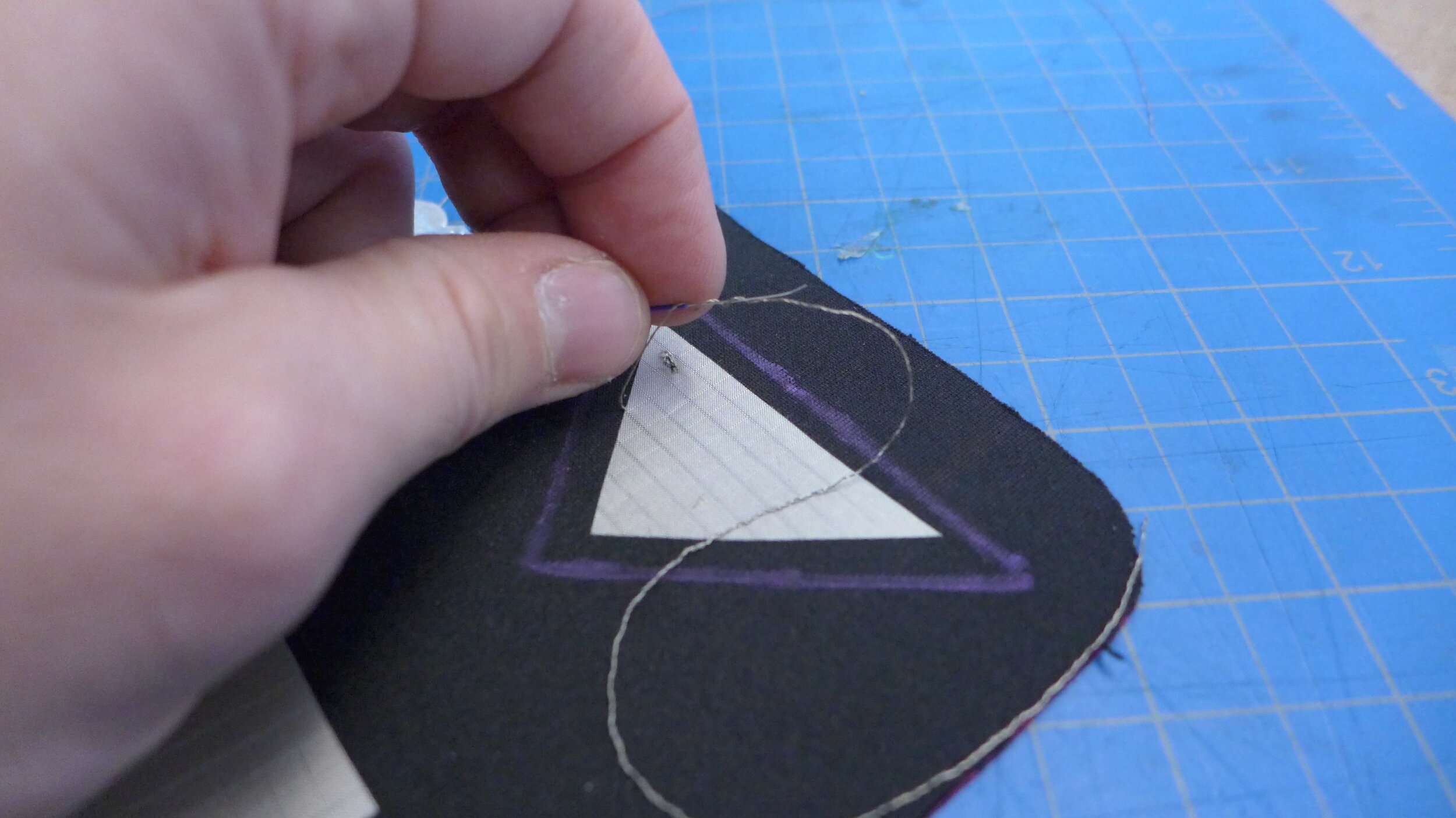
Velostat pressure-sensing material
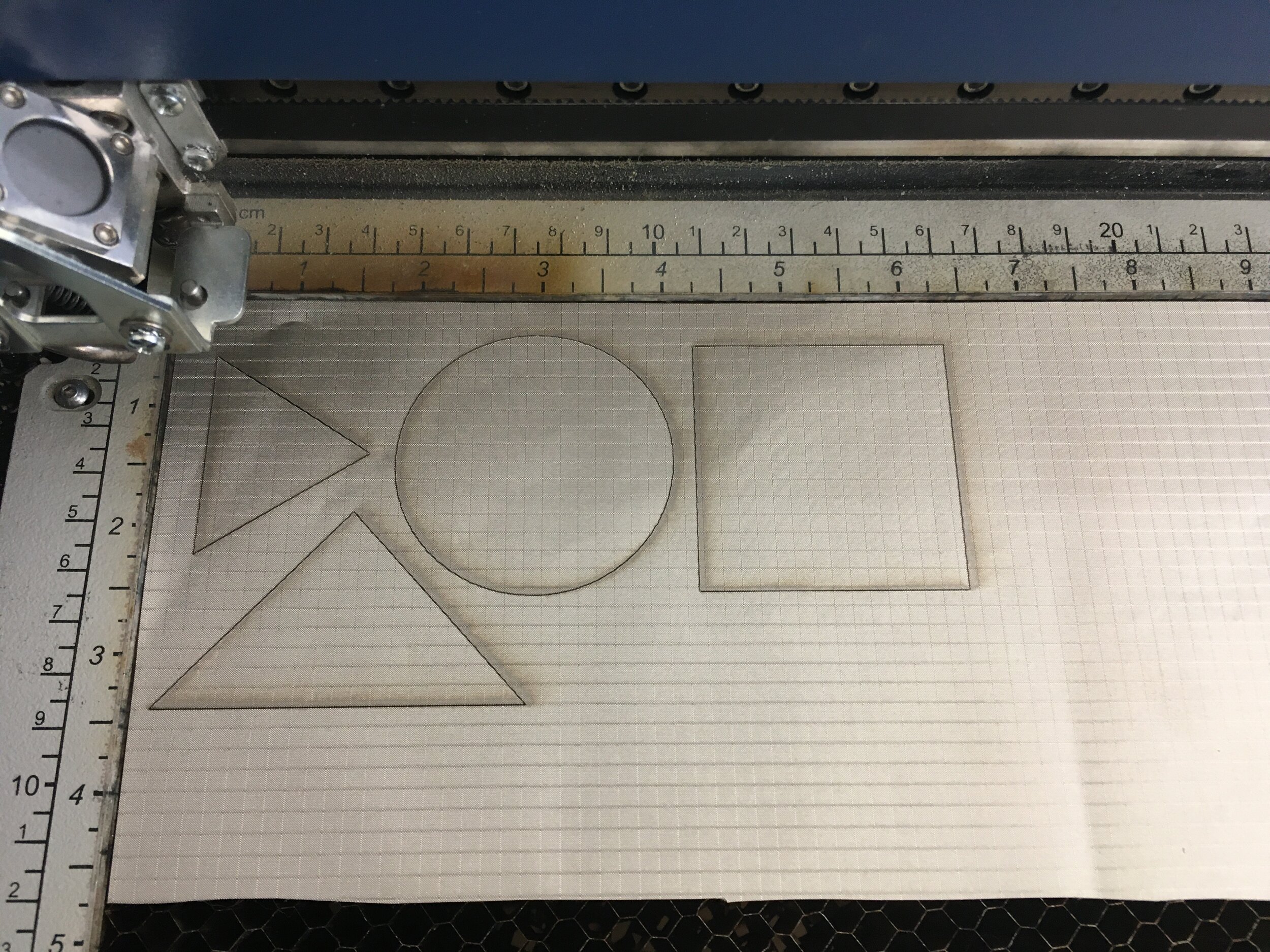
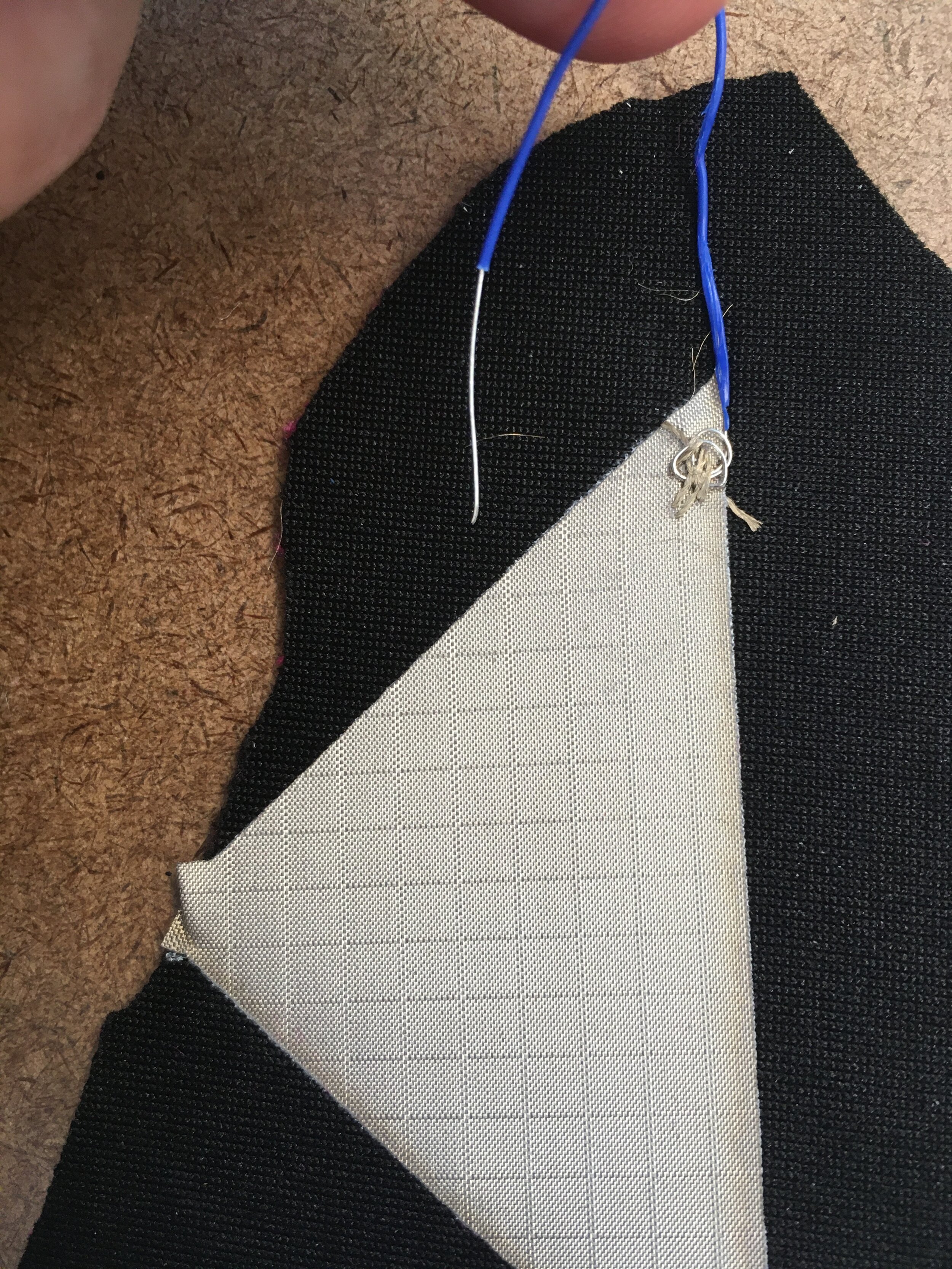
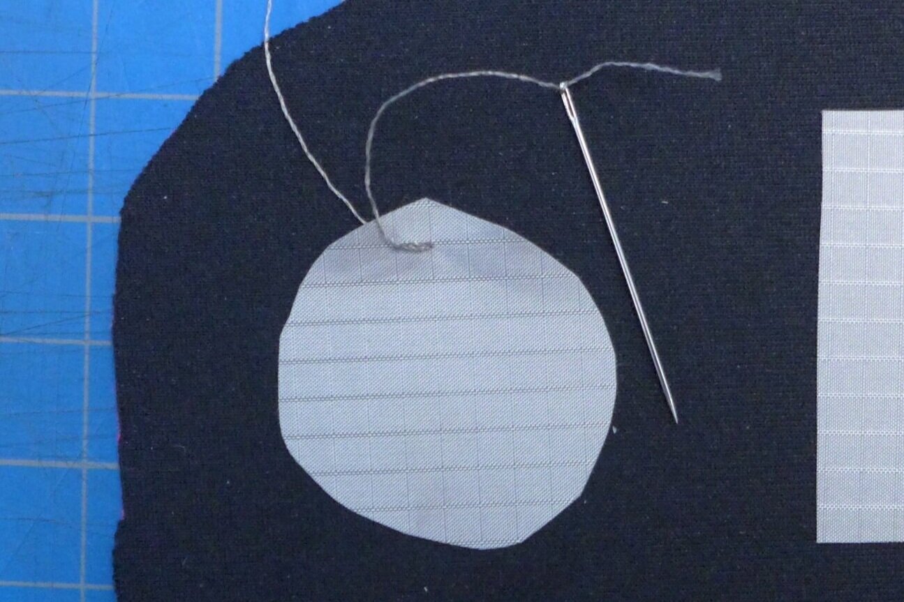
Conductive fabric
Neoprene
Laser cutter
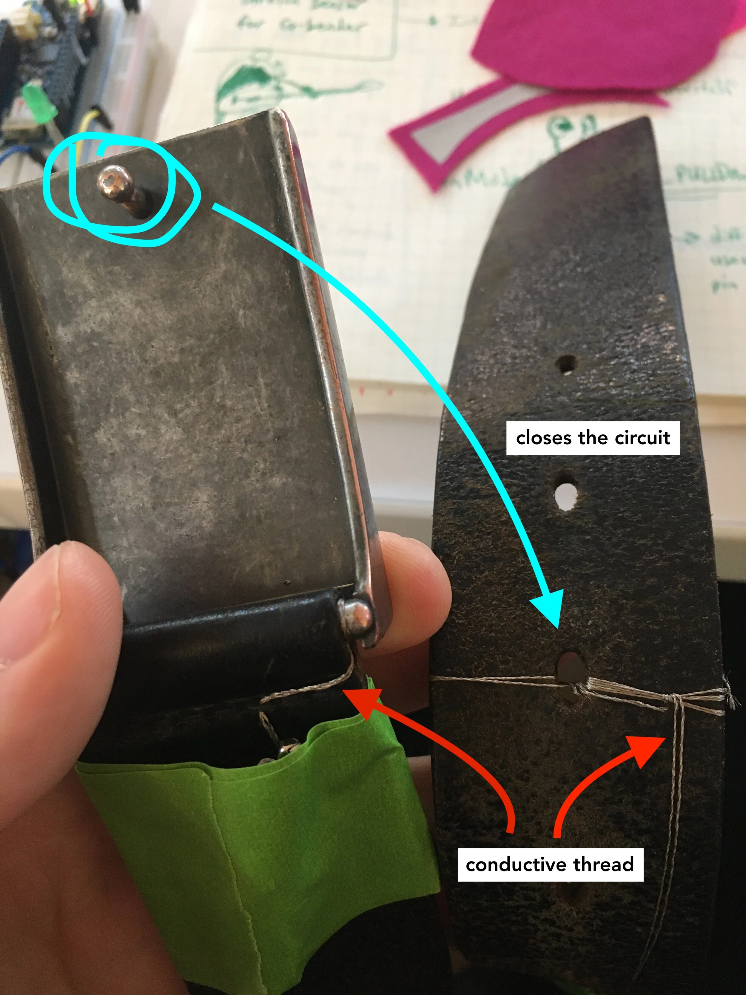
Conductive thread
Vectorworks
MaxMSP
Ableton Live
C++
OSC/UDP network communication